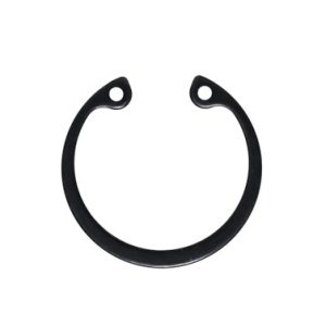
In mechanical engineering, securing components onto shafts or inside bores without adding excessive weight or bulk is a foundational challenge. The industry standard solutions for this are DIN 471 and DIN 472 circlips—also known as retaining rings. Though they look similar to the untrained eye, these two fasteners serve opposite geometric purposes. Understanding their differences, installation methods, and failure modes is critical for ensuring machinery longevity and safety.
The Core Difference: External vs. Internal
The fundamental distinction between DIN 471 and DIN 472 lies in where they are mounted and how they exert their spring force.
- DIN 471 (External Circlips): These are designed to secure components onto the outside of a shaft. They are installed into a machined groove on the shaft’s exterior. To fit them, the ring must be expanded outward using specialised pliers. Once released, the ring tightly grips the bottom of the groove. The lug ears (the tips with the small holes) point outward so they do not interfere with the shaft surface.
- DIN 472 (Internal Circlips): These are engineered to retain components inside a bore or housing. They fit into a groove machined into the internal wall of a hole. During installation, the ring is compressed inward. Once inside the bore and aligned with the groove, it expands outward to lock itself into place. The lug ears point inward to prevent interference with the housing wall.
Design, Geometry, and Materials
Both standards dictate a tapered radial wall design. The ring is thickest opposite the opening and tapers down toward the lugs. This specific geometry ensures that the circlip maintains a perfectly circular shape when expanded or compressed, distributing clamping pressure evenly around the entire circumference of the groove.
Critical Engineering Considerations
Successfully implementing DIN 471 and DIN 472 circlips requires precise calculation of the application’s mechanical limits:
- Groove Dimensions: The depth, width, and sharpness of the groove radii are strictly defined by the DIN standards. If a groove is machined too shallow, the ring will not seat completely, drastically reducing its load capacity.
- Thrust Load Capacity: Circlips are designed to withstand axial forces (forces pushing along the length of the shaft or bore). This capacity is split into two limits: the shear strength of the circlip itself and the load-bearing wall strength of the groove material. If the groove material (e.g., aluminium) is softer than the spring steel circlip, the groove wall will fail long before the circlip shears.
- Centrifugal Force (DIN 471 specific): Because external circlips cling to a shaft, high-speed rotation can cause centrifugal force to expand the ring outward. If the shaft spins fast enough, the circlip can lift out of its groove entirely. For high-RPM applications, special self-locking circlips or heavy-duty variations must be used.
Best Practices for Installation and Maintenance
Improper handling is the leading cause of circlip failure. Engineers and technicians should adhere to the following guidelines:
- Use the Right Tools: Always use dedicated circlip pliers (external pliers for DIN 471, internal pliers for DIN 472). Using screwdrivers or makeshift tools bends the rings permanently.
- Avoid Over-stressing: Only expand or compress the ring just enough to clear the shaft or enter the bore. Over-stretching exceeds the material’s elastic limit, leaving the ring permanently deformed. A loose circlip will quickly vibrate out of its groove.
- Orientation Matters: Circlips are stamped out of sheet metal, leaving one sharp edge and one slightly rounded edge. The sharp edge should always face away from the retained part to ensure maximum contact area against the groove wall.
- Never Reuse Stressed Rings: If a circlip has been removed during maintenance and shows signs of permanent distortion or loss of tension, it must be discarded and replaced.