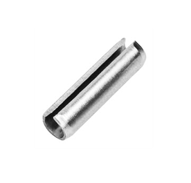
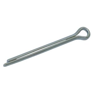
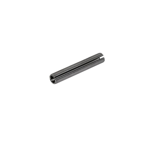
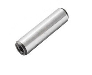
In demanding engineering applications, component longevity is non-negotiable. Our Stainless Steel Spring Tension Pins provide an exceptionally reliable, self-retaining fastening solution that eliminates the need for precision-reamed holes.
Whether you are pinning shafts, locking gears, or securing hinges, our slotted pins self-center and self-lock to drastically cut down your assembly time and production costs.
Stop worrying about mechanical failure. Lock your assemblies in place with the ultimate industrial fastener.
In high-stress mechanical engineering, maintaining the exact preload of a bolted joint is critical to system safety and longevity. When assemblies encounter heavy vibrations, thermal expansion, or material settling, standard fasteners often experience clamp-load loss. This is where DIN 6796 conical spring washers—frequently referred to as heavy-duty Belleville washers—become essential components.
What is a DIN 6796 Disc Spring?
Manufactured to strict German standards, DIN 6796 specifies heavy-duty conical spring washers designed specifically for bolted connections. Unlike a standard flat washer, a DIN 6796 washer has a distinct, shallow conical profile. As a bolt or nut is tightened, the washer is flattened, generating a continuous axial spring force against the fastening assembly. This controlled spring action absorbs minute movements and physical relaxation within the joint, maintaining a highly secure, frictional locking effect.
Mechanical Capabilities and Specifications
These heavy-duty washers are built to withstand immense forces in tight, compact spaces. When fully compressed, the force generated by a DIN 6796 washer equals roughly 70% to 90% of the contact pressure required for high-tensile property class 8.8 and 10.9 bolts.
Primary Industrial Applications
Because they prevent catastrophic loosening from thermal cycling and high fatigue, DIN 6796 heavy-duty disc springs are widely used across the energy, aerospace, automotive, and heavy manufacturing sectors. You will regularly find them deployed in:
Heavy bolted sections including industrial pipe flanges, electrical transformers, and high-voltage bus-bars.
High-torque industrial machinery, fabrication equipment, and structural steel connections.
Pressure control systems, industrial regulators, and heavy-duty braking assemblies.
For a quote for these parts in bespoke materials such as Inconel, please contact us today.
To browse our standard DIN 6796 range online, please click here.
Delta Tone Disc Springs (Belleville Washers) are high-performance conical spring washers coated with an inorganic zinc-flake surface treatment to provide exceptional corrosion resistance without risking structural failure. In heavy-duty mechanical engineering, managing immense axial loads in tight spaces is a standard requirement. However, introducing high-stress components to harsh environments frequently leads to a compromise between strength and environmental degradation. This specialized combination addresses that exact vulnerability.
To understand why Delta Tone is so highly regarded, it helps to look at the unique manufacturing trap it avoids. Standard high-strength carbon steel or chrome vanadium disc springs are highly susceptible to hydrogen embrittlement. When these springs undergo traditional electroplating, hydrogen gas can be absorbed into the steel structure, making it dangerously brittle and prone to sudden, catastrophic cracking under load.
Delta Tone circumvents this danger entirely. Applied as an inorganic coating made up of carefully blended aluminium and zinc compounds, it is baked directly onto the surface. Because the application is non-electrolytic, there is zero risk of hydrogen absorption. The baking process cures the material into a bright silver, highly flexible barrier that bends and flexes naturally with the extreme deflection of the spring without chipping or peeling.
When combined with an organic topcoat like Delta Seal, this pairing delivers a massive boost in longevity. In industrial salt spray and stress corrosion cracking tests, Delta Tone-treated parts regularly withstand hundreds of hours of exposure far better than standard oiled or mechanically zinc-plated alternatives. Furthermore, it creates a crucial bimetallic barrier that prevents galvanic corrosion when the steel spring is compressed directly against aluminium components.
For modern engineering teams focused on sustainability, Delta Tone offers an additional compliance advantage. The formulation is completely free of heavy metals—such as hexavalent chromium, cadmium, or lead—ensuring total alignment with strict global environmental standards like RoHS and ELV directives.
Whether utilized in high-vibration automotive subassemblies, industrial valves, or heavy manufacturing machinery, opting for Delta Tone disc springs guarantees that your critical components retain their exact force-deflection characteristics without yielding to rust or micro-cracking. It represents a highly cost-effective insurance policy for demanding hardware operating in unpredictable environments.
Please contact us today for a free quotation for our Delta-Tone Disc Springs.
Manufactured from premium-grade carbon spring steel, these external circlips are treated to deliver the perfect balance of hardness and elasticity. They grip tightly, expand reliably over shafts without permanent distortion, and withstand intense centrifugal forces across automotive, manufacturing, and heavy engineering applications.
Why Engineers Choose Us:
Massive Stockholding: Immediate availability on all standard metric and imperial shaft sizes.
Bulk Trade Pricing: Highly competitive rates and flexible scheduled ordering for high-volume manufacturing lines.
Next-Day UK Delivery: Keep your production schedules moving with our rapid, dependable dispatch network.
Secure Your Inventory Today
Don’t risk component migration with inferior fasteners. Trust the UK’s leading distributor for reliable, carbon steel external circlips.
When we think about engineering failures, we often picture massive structural breaks or dramatic engine meltdowns. But more often than not, catastrophic failures start with something incredibly small: a single nut or bolt backing off due to constant vibration.
While standard flat washers are great for distributing weight, they do very little to stop a fastener from spinning free under stress. That is where internal shakeproof washers (often called internal tooth or serrated lock washers) come into play.
Here is a breakdown of how these small components provide maximum security, why their internal design matters, and where they are best utilized.
How Internal Shakeproof Washers Work
Unlike standard hardware, an internal shakeproof washer relies on mechanical tension and physical friction.
The Tooth Design: The inner rim of the washer features a series of twisted, sharp prongs or teeth.
The Bite: As you tighten a nut or bolt down onto the washer, these teeth flatten under the pressure.
The Lock: The spring tension forces the sharp edges of the teeth to bite directly into the underside of the fastener head and the mating surface. If vibrations try to back the bolt out, the angled teeth dig deeper, preventing rotation.
In the world of mechanical engineering and machinery restoration, it is often the smallest components that carry the heaviest responsibilities. Enter the humble cotter pin (or split pin, as it is frequently called). While modern industrial manufacturing has largely shifted toward metric standards, imperial cotter pins remain an absolute staple for engineers, mechanics, and vintage restoration enthusiasts.
Whether you are working on a classic British tractor, a vintage American muscle car, or heavy-duty agricultural equipment, understanding imperial cotter pins is vital to keeping your machinery safely locked in place.
What is a Cotter Pin?
A cotter pin is a simple yet incredibly reliable wire-formed fastener. It features a semi-round cross-section bent in half to create a bulbous, rounded eyelet head at one end and two unequal tines (or prongs) at the other.
The mechanism is beautifully simple: the pin is inserted through a pre-drilled transverse hole—typically in a clevis pin, an axle, or a bolt paired with a castellated (castle) nut. Once the pin is pushed through until the head sits flush, the two tines are bent outward in opposite directions. This deformation creates a permanent mechanical lock, ensuring that the nut or component cannot vibrate loose or back off under dynamic loads.
What is a Cotter Pin?
A cotter pin is a simple yet incredibly reliable wire-formed fastener. It features a semi-round cross-section bent in half to create a bulbous, rounded eyelet head at one end and two unequal tines (or prongs) at the other.
The mechanism is beautifully simple: the pin is inserted through a pre-drilled transverse hole—typically in a clevis pin, an axle, or a bolt paired with a castellated (castle) nut. Once the pin is pushed through until the head sits flush, the two tines are bent outward in opposite directions. This deformation creates a permanent mechanical lock, ensuring that the nut or component cannot vibrate loose or back off under dynamic loads.
Why “Imperial” Still Matters
With the global standardisation of the metric system, you might wonder why imperial cotter pins are still widely manufactured and stocked. The answer lies in legacy, longevity, and specific regional industries.
Vintage and Classic Restorations: Classic cars, motorcycles, and steam engines built to American or historical British standards rely entirely on fractional inch measurements. Forcing a metric pin into an imperial hole can lead to dangerous play or a fit that is too tight to properly secure.
Agricultural Equipment: A massive amount of legacy farm machinery still actively in use across North America and Australia was originally manufactured to imperial specifications.
Heavy Industry and Aerospace: Certain heavy industrial plants and specific sectors of aerospace still maintain fractional standards for specialized hardware.
Installing a slotted spring pin (or “roll pin”) looks incredibly straightforward, but doing it wrong can result in bent pins, damaged workpieces, or a loose fit. Because these pins rely on outward radial tension to stay locked in place, precise installation is key.
Whether you are working with a hammer and punch or using automated machinery, here is the proper way to insert a slotted spring pin.
1. Match the Hole and Pin Size
Slotted spring pins are designed to be pressed into standard, plain drilled holes. Because the pin itself is manufactured slightly oversized, never drill the hole larger than the nominal diameter of the pin.
For a 1/4-inch pin, drill a standard 1/4-inch hole.
The pin’s built-in elasticity will handle the compression, creating the tight friction-fit needed to stay secure.
2. Chamfer the Hole Entrance (Highly Recommended)
While slotted spring pins feature bevelled or chamfered ends to help guide them into place, prepping the hole makes a massive difference.
Use a deburring tool or a countersink bit to create a tiny bevel at the entrance of the hole.
This smooth transition prevents the sharp edges of the pin from shaving metal off the inside of the hole during insertion, which can ruin the tight fit.
3. Choose the Right Tools
For Manual Installation: Never use a standard flat-face punch. You need a roll pin punch (or spring pin punch). These specialty punches feature a small, raised ball or pilot point in the center of the tip. This point seats perfectly inside the hollow center of the pin, preventing the punch from slipping off and keeping the driving force perfectly centered.
For Production Environments: Use an arbor press or a pneumatic press equipped with a dedicated pin-driving mandrel.
4. Position and Align the Pin
Align your workpieces so the pre-drilled holes are perfectly concentric. Place the chamfered end of the pin into the hole.
Orientation Matters: If the pin will be subjected to a specific directional load, orient the longitudinal slot away from the direction of the force (typically 90 degrees to the load vector) to maximize the pin’s shear strength and structural integrity.
5. Drive the Pin Home
Manual Method: Hold the pin straight with a pair of pliers or a pin starter tool. Tap the pin gently with a ball-peen hammer until it takes hold in the hole. Once it supports itself, place your roll pin punch over the head of the pin and drive it straight down with firm, consistent hammer blows.
Press Method: Lower the press ram smoothly. Ensure the force is applied completely perpendicular to the workpiece to prevent bending the pin.
6. Verify Final Depth
Drive the pin until it sits exactly where you need it.
For a standard flush fit, the pin should sit slightly below the surface of the host material (typically about 0.5 mm to 1 mm deep).
If the pin is serving as a pivot or hinge, ensure it extends equally out of both sides of the moving component.
DIN 7979D extractable dowel pins are precision-engineered parallel engineering alignment fasteners. Commonly known as pull dowels, they feature a tapped internal thread at one end to allow quick extraction via an eye bolt, puller screw, or slide hammer. These heavy-duty components are through-hardened and precision-ground to an m6 interference fit tolerance to ensure dead-accurate positioning within jigs, fixtures, press tools, and mould dies.
Key Engineering Highlights
Zero Hydraulics: Built with a standardized air release flat along the side of the pin body. This flat bleeds out trapped pressure during installation, allowing smooth placement into blind holes without air resistance or hydraulic locking.
Extreme Longevity: Manufactured from premium through-hardened alloy steel (such as 100Cr6 steel) hardened to a rating of 57-64 HRC. This high hardness yields severe wear resistance and prevents pin deformation under brutal shear loads.
Simple Extraction: Simplifies maintenance schedules by eliminating the need to drill out pins or use destructive punch methods. A simple matching machine screw can pull the pin straight out without damaging adjacent workpieces
Often referred to simply as key bar or keysteel, Imperial Key Steel is a high-precision, bright-drawn steel bar available in traditional inch-based measurements. It is engineered with extremely tight dimensional tolerances, allowing it to be cut down and fitted directly into matching keyways on shafts and rotating machine parts.
Square vs. Rectangular Profiles
Depending on the mechanical configuration, imperial key steel is supplied in two primary cross-sectional formats:
Square Profile: Equal thickness on all sides (e.g., 1/4″ x 1/4″ or 3/8″ x 3/8″). This is widely used for standard parallel keys.
Flat/Rectangular Profile: Unequal dimensions (e.g., 1/2″ x 3/8″). These are engineered for specific mechanical tolerances or low-profile keyway channels.
Where is it Used?
Imperial key steel remains incredibly vital for servicing legacy systems, vintage vehicles, agricultural equipment, and specialized industrial gearboxes designed before the widespread adoption of the metric system.
In engineering and manufacturing, vibration is the ultimate silent enemy. From household appliances to high-velocity automotive engines, constant movement creates micro-shifts that can cause standard nuts and bolts to back off and fail.
While a traditional flat washer excels at distributing weight, it does very little to stop a bolt from spinning loose. Enter the shakeproof washer (also known as a tooth lock washer). This specialized component uses mechanical tension and physical barriers to lock fasteners firmly in place.
Here is everything you need to know about how these small components solve massive mechanical issues.
How Do Shakeproof Washers Work?
Unlike a smooth flat washer, a shakeproof washer features a series of sharp, twisted teeth along its edges.
When you tighten a nut or bolt down onto a shakeproof washer, these teeth act like microscopic anchors. The twisted configuration means one edge of the tooth bites directly into the underside of the fastener head, while the opposite edge digs into the mating surface.
This aggressive dual-bite prevents the fastener from turning backwards. Additionally, the minor spring-like tension within the teeth absorbs ongoing vibrations, maintaining structural friction even under heavy workloads.
Internal vs. External: Choosing Your Type
Shakeproof washers generally fall into two primary configurations based on where their teeth are located. Choosing the right one depends heavily on your workspace and cosmetic goals.
Washer Type
Teeth Location
Best Used For…
Key Benefit
Internal Serrated
Inside diameter
Small fastener heads and tight assembly spaces.
Provides a clean, hidden finish after tightening.
External Serrated
Outside diameter
Larger fastener heads and maximum locking power.
Teeth bite further away from the axis, offering better torque resistance.
Most shakeproof washers are finished in a bright zinc plating (BZP) for general corrosion resistance.