Category Archives: Uncategorised

Maintaining Bolted Joint Integrity with DIN 6796 Conical Spring Washers

In high-stress mechanical engineering, maintaining the exact preload of a bolted joint is critical to system safety and longevity. When assemblies encounter heavy vibrations, thermal expansion, or material settling, standard fasteners often experience clamp-load loss. This is where DIN 6796 conical spring washers—frequently referred to as heavy-duty Belleville washers—become essential components.

What is a DIN 6796 Disc Spring?

Manufactured to strict German standards, DIN 6796 specifies heavy-duty conical spring washers designed specifically for bolted connections. Unlike a standard flat washer, a DIN 6796 washer has a distinct, shallow conical profile. As a bolt or nut is tightened, the washer is flattened, generating a continuous axial spring force against the fastening assembly. This controlled spring action absorbs minute movements and physical relaxation within the joint, maintaining a highly secure, frictional locking effect.

Mechanical Capabilities and Specifications

These heavy-duty washers are built to withstand immense forces in tight, compact spaces. When fully compressed, the force generated by a DIN 6796 washer equals roughly 70% to 90% of the contact pressure required for high-tensile property class 8.8 and 10.9 bolts.

Primary Industrial Applications

Because they prevent catastrophic loosening from thermal cycling and high fatigue, DIN 6796 heavy-duty disc springs are widely used across the energy, aerospace, automotive, and heavy manufacturing sectors. You will regularly find them deployed in:

  • Heavy bolted sections including industrial pipe flanges, electrical transformers, and high-voltage bus-bars.
  • High-torque industrial machinery, fabrication equipment, and structural steel connections.
  • Pressure control systems, industrial regulators, and heavy-duty braking assemblies.

For a quote for these parts in bespoke materials such as Inconel, please contact us today.

To browse our standard DIN 6796 range online, please click here.

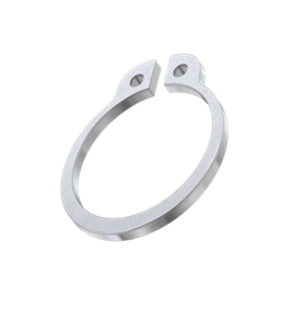
External Circlips: Heavy-Duty Performance. Uncompromised Strength.

Manufactured from premium-grade carbon spring steel, these external circlips are treated to deliver the perfect balance of hardness and elasticity. They grip tightly, expand reliably over shafts without permanent distortion, and withstand intense centrifugal forces across automotive, manufacturing, and heavy engineering applications.

Why Engineers Choose Us:

  • Massive Stockholding: Immediate availability on all standard metric and imperial shaft sizes.
  • Bulk Trade Pricing: Highly competitive rates and flexible scheduled ordering for high-volume manufacturing lines.
  • Next-Day UK Delivery: Keep your production schedules moving with our rapid, dependable dispatch network.

Secure Your Inventory Today

Don’t risk component migration with inferior fasteners. Trust the UK’s leading distributor for reliable, carbon steel external circlips.

A Guide to Imperial Cotter Pins

In the world of mechanical engineering and machinery restoration, it is often the smallest components that carry the heaviest responsibilities. Enter the humble cotter pin (or split pin, as it is frequently called). While modern industrial manufacturing has largely shifted toward metric standards, imperial cotter pins remain an absolute staple for engineers, mechanics, and vintage restoration enthusiasts.

Whether you are working on a classic British tractor, a vintage American muscle car, or heavy-duty agricultural equipment, understanding imperial cotter pins is vital to keeping your machinery safely locked in place.

What is a Cotter Pin?

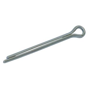
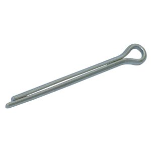
A cotter pin is a simple yet incredibly reliable wire-formed fastener. It features a semi-round cross-section bent in half to create a bulbous, rounded eyelet head at one end and two unequal tines (or prongs) at the other.

The mechanism is beautifully simple: the pin is inserted through a pre-drilled transverse hole—typically in a clevis pin, an axle, or a bolt paired with a castellated (castle) nut. Once the pin is pushed through until the head sits flush, the two tines are bent outward in opposite directions. This deformation creates a permanent mechanical lock, ensuring that the nut or component cannot vibrate loose or back off under dynamic loads.

What is a Cotter Pin?

A cotter pin is a simple yet incredibly reliable wire-formed fastener. It features a semi-round cross-section bent in half to create a bulbous, rounded eyelet head at one end and two unequal tines (or prongs) at the other.

The mechanism is beautifully simple: the pin is inserted through a pre-drilled transverse hole—typically in a clevis pin, an axle, or a bolt paired with a castellated (castle) nut. Once the pin is pushed through until the head sits flush, the two tines are bent outward in opposite directions. This deformation creates a permanent mechanical lock, ensuring that the nut or component cannot vibrate loose or back off under dynamic loads.

Why “Imperial” Still Matters

With the global standardisation of the metric system, you might wonder why imperial cotter pins are still widely manufactured and stocked. The answer lies in legacy, longevity, and specific regional industries.

  • Vintage and Classic Restorations: Classic cars, motorcycles, and steam engines built to American or historical British standards rely entirely on fractional inch measurements. Forcing a metric pin into an imperial hole can lead to dangerous play or a fit that is too tight to properly secure.
  • Agricultural Equipment: A massive amount of legacy farm machinery still actively in use across North America and Australia was originally manufactured to imperial specifications.
  • Heavy Industry and Aerospace: Certain heavy industrial plants and specific sectors of aerospace still maintain fractional standards for specialized hardware.

How to Properly Install Slotted Spring Pins: A Step-by-Step Guide

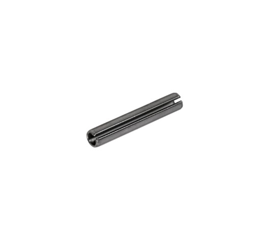
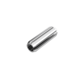
Installing a slotted spring pin (or “roll pin”) looks incredibly straightforward, but doing it wrong can result in bent pins, damaged workpieces, or a loose fit. Because these pins rely on outward radial tension to stay locked in place, precise installation is key.

Whether you are working with a hammer and punch or using automated machinery, here is the proper way to insert a slotted spring pin.

1. Match the Hole and Pin Size

Slotted spring pins are designed to be pressed into standard, plain drilled holes. Because the pin itself is manufactured slightly oversized, never drill the hole larger than the nominal diameter of the pin.

  • For a 1/4-inch pin, drill a standard 1/4-inch hole.
  • The pin’s built-in elasticity will handle the compression, creating the tight friction-fit needed to stay secure.

2. Chamfer the Hole Entrance (Highly Recommended)

While slotted spring pins feature bevelled or chamfered ends to help guide them into place, prepping the hole makes a massive difference.

  • Use a deburring tool or a countersink bit to create a tiny bevel at the entrance of the hole.
  • This smooth transition prevents the sharp edges of the pin from shaving metal off the inside of the hole during insertion, which can ruin the tight fit.

3. Choose the Right Tools

  • For Manual Installation: Never use a standard flat-face punch. You need a roll pin punch (or spring pin punch). These specialty punches feature a small, raised ball or pilot point in the center of the tip. This point seats perfectly inside the hollow center of the pin, preventing the punch from slipping off and keeping the driving force perfectly centered.
  • For Production Environments: Use an arbor press or a pneumatic press equipped with a dedicated pin-driving mandrel.

4. Position and Align the Pin

Align your workpieces so the pre-drilled holes are perfectly concentric. Place the chamfered end of the pin into the hole.

  • Orientation Matters: If the pin will be subjected to a specific directional load, orient the longitudinal slot away from the direction of the force (typically 90 degrees to the load vector) to maximize the pin’s shear strength and structural integrity.

5. Drive the Pin Home

  • Manual Method: Hold the pin straight with a pair of pliers or a pin starter tool. Tap the pin gently with a ball-peen hammer until it takes hold in the hole. Once it supports itself, place your roll pin punch over the head of the pin and drive it straight down with firm, consistent hammer blows.
  • Press Method: Lower the press ram smoothly. Ensure the force is applied completely perpendicular to the workpiece to prevent bending the pin.

6. Verify Final Depth

Drive the pin until it sits exactly where you need it.

  • For a standard flush fit, the pin should sit slightly below the surface of the host material (typically about 0.5 mm to 1 mm deep).
  • If the pin is serving as a pivot or hinge, ensure it extends equally out of both sides of the moving component.

📏 Split Cotter Pins: Finding the right size

To identify the right size split cotter pin, you must match the nominal diameter of the pin to the diameter of the drilled hole, and ensure the effective length is long enough to bend after passing completely through the assembly.

Split cotter pins (governed by standards like DIN 94) are uniquely sized by the hole they are fitting into, not the actual width of the wire

1. Determine the Diameter

  • Measure the Hole: Use a vernier caliper, drill bit, or pin gauge to measure the inside diameter of the hole you are trying to fill.
  • Match the Nominal Size: If your hole measures 4 mm, you need a 4 mm nominal split pin.
  • The Manufacturer’s Clearance: Do not worry if the actual wire thickness feels slightly smaller when you measure it with calipers. Under DIN 94 Standards, the actual pin diameter is manufactured undersize so it slides through the hole smoothly without lateral play.
  • Avoid Under-Sizing: Never use a pin that is too small for the hole. Vibration will cause a loose pin to wear the hole into an oval shape over time, leading to eventual mechanical failure.

2. Determine the Effective Length

  • Measure the Component Thickness: Measure the total distance the pin needs to travel (e.g., the width of the shaft or the distance through a castle nut).
  • Account for the Prongs: The “effective length” of a split pin is measured from the underside of the loop (the head) to the tip of the shortest leg.
  • Add Clearance for Bending: Choose a length where both legs extend past the exit hole by at least the thickness of the pin’s diameter. This ensures you have enough leverage to bend the tines back securely with pliers.

You can order these parts in Mild Steel Zinc Plate and Stainless Steel through our online store.

INCONEL® Circlips / Retaining Rings – Uncompromising Retaining Power for Extreme Environments

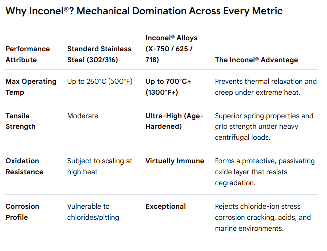
When standard carbon or stainless steel circlips fail under violent temperatures and aggressive corrosion, Inconel® Circlips keep your critical assemblies locked tight. Engineered for high-stress aerospace, automotive, and marine environments, these circlips provide ultimate structural integrity where mechanical failure is not an option.

Engineered for Industry-Critical Applications

  • Aerospace & Aviation: Securing turbine assemblies, exhaust systems, and fuel control valves subject to rapid thermal cycling.
  • Motorsport & Performance Automotive: Critical retention inside turbochargers, high-performance valvetrains, and exhaust manifolds.
  • Oil, Gas & Petrochemical: Downhole drilling tools, subsea valves, and process piping exposed to sour gas (H₂S) and high pressures.
  • Marine Engineering: Fasteners and shafts continuously submerged in highly corrosive seawater environments.

Upgrade to Absolute Reliability. Request a Quote Today.

Don’t let a minor component cause a catastrophic system failure. Switch to the unyielding strength of Inconel Circlips.

📥 Contact our Sales Team today at sales@calebcomponents.com or call us on +44 (0)121 661 6664

The Invisible Anchor: A Complete Guide to Stainless Steel Spring Pins

In the world of manufacturing, maintenance, and product design, engineers are constantly looking for fasteners that balance strength, ease of installation, and cost-efficiency. Threaded bolts require tapped holes, rivets are permanent, and solid dowel pins demand absolute, microscopic precision during drilling.

Enter the stainless steel spring pin (also widely known as a roll pin or slotted pin).

What is a Stainless Steel Spring Pin?

A spring pin is a hollow, cylindrical fastener with a longitudinal slot or a coiled cross-section. They are intentionally manufactured with an outer diameter (OD) slightly larger than the hole into which they will be installed.

     Slotted Spring Pin                 Coiled Spring Pin
       _____________                      _____________

      |   _______   |                    |  _________  |
      |  |       |  |                    | |  _____  | |
      |  | [Slot] |  |                    | | |     | | |
      |  |_______|  |                    | |_|_____|_| |
      |_____________|                    |_____________|
    (Flexes via single slot)            (Flexes like a coil sheet)

As the pin is driven into the hole, its spring-like construction allows it to compress. The continuous outward radial force exerted by the pin against the hole wall creates a powerful friction lock, ensuring it stays firmly anchored without the need for nuts, threads, or retaining rings.

Whether you are anchoring a gear to a shaft, building a rugged outdoor hinge, or assembling precision medical equipment, stainless steel spring pins provide a low-cost, high-reliability solution. They cut down on machining time by eliminating the need for tapped threads, while their innate spring tension guarantees they won’t vibrate loose under stress.

Grip Rings: The Hidden Hero of Grooveless Shafts

When building or repairing machinery, we often take the smallest fasteners for granted. Standard circlips and retaining rings usually require a pre-machined groove on a shaft to sit correctly. But what happens if you cannot machine a groove? Or what if doing so blows past your production budget?

Enter the M1440 Grip Ring series, a specialized line of self-locking, axially fitted metric circlips designed specifically to provide strong retention on shafts without pre-machined grooves. By relying purely on frictional grip and high radial pressure, these unassuming components act as a powerful fastening alternative across countless industrial applications.

What Makes the M1440 Grip Ring Unique?

Unlike a standard DIN 471 external circlip that relies on a channel to hold its place, the M1440 series is engineered with a large section height. This design results in massive gripping pressure applied directly to the surface of the plain shaft.

   [ Standard Circlip ]           [ M1440 Grip Ring ]
     Requires Groove                 Grooveless Shaft
       ___       ___                    ___________

      |   |_____|   |                  |   _____   |
=====>|   |     |   | =====>      ====>|  |     |  |====>

      |___|  _  |___|                  |__|_____|__|
             |                               |
       Seated in Groove                Frictional Grip

A major engineering benefit of the M1440 design is its tapered section. When fitted, this taper ensures even contact distribution around the entire circumference of the shaft. Because the ring is not stretched beyond its elastic limit during installation or removal, it can be re-used multiple times without losing its gripping force or damaging the shaft.

You will find M1440 grip rings quietly doing heavy lifting behind the scenes across a vast range of sectors:

  • Automobile Assemblies: Securing lightweight linkages and pivot pins where structural machining is impractical.
  • Industrial & Manufacturing Machinery: Acting as quick-fix or adjustable retaining stops on automated conveyor lines and guide rods.
  • Office & Domestic Furniture: Holding rotating wheels, casters, or small internal hinges firmly in place on plain steel pins.

High Performance Under Pressure: Disc Springs in Aerospace Engineering

In aerospace design, every component must deliver maximum reliability with minimum weight. Space is limited, and environmental conditions are extreme. Disc springs—also known as Belleville washers—are conical-shaped metallic rings that solve these precise engineering challenges. They store and release mechanical energy along their axial axis, offering unique force-displacement characteristics that standard coil springs cannot match.

Here is an analysis of how these compact components support critical aerospace systems.

Exceptional Load-Bearing Capabilities:

Disc springs are uniquely suited for aerospace applications due to their high force-to-space ratio.

  • Space Efficiency: They generate immense force within a highly compact physical footprint.
  • Customisable Stack Dynamics: Engineers can stack discs in series to increase deflection, or in parallel to multiply the load capacity.
  • Predictable Deflection Curves: They can be engineered to exhibit linear, regressive, or progressive load characteristics based on the application’s specific mechanical requirements.

Critical Aerospace Applications

Disc springs act as vital safeguards across multiple aircraft and spacecraft subsystems.

Flight Control Systems:

In hydraulic actuators and primary flight control linkages, disc springs maintain constant tension. They take up mechanical backlash, ensuring that pilot inputs or automated flight corrections remain precise and instantaneous without slop in the system.

Landing Gear Assemblies:

Aircraft landing gear must absorb massive kinetic energy during touchdown. Disc springs are utilized within shock absorption systems and braking mechanisms. They provide heavy-duty dampening and maintain consistent pressure on brake packs as friction materials wear down over time.

Cryogenic and High-Temperature Valves:

Spacecraft and rocket propulsion systems rely on valves that operate anywhere from cryogenic liquid fuel temperatures to extreme exhaust heat. Disc springs exert continuous sealing pressure on valve seats, automatically compensating for the thermal expansion and contraction of surrounding metals to prevent catastrophic leaks.

Bolt Preloading and Structural Joints:

Aerospace structures experience severe vibration during flight and launch. Disc springs are placed under bolt heads and nuts to maintain a constant pre-load. This prevents structural fasteners from loosening under cyclical stress and vibration.

Advanced Metallurgy and Material Selection:

Standard carbon steel fails under the extreme demands of flight. Aerospace disc springs utilize advanced alloys engineered to survive corrosive environments, high radiation, and thermal spikes.

  • Inconel (X750 and 718): Chosen for its exceptional strength and resistance to relaxation at high temperatures.
  • Titanium Alloys: Utilized when weight reduction is the primary design driver, offering an excellent strength-to-weight ratio.
  • Stainless Steels (e.g., 17-7 PH): Selected for high fatigue resistance and excellent corrosion protection in atmospheric flight.

Strict Manufacturing and Quality Standards:

Failure is not an option in aerospace engineering. The production of aerospace-grade disc springs requires meticulous quality control processes.

  • Precision Machining: Involves tight tolerances on the inner diameter, outer diameter, and material thickness to ensure predictable force profiles.
  • Shot Peening: A surface treatment process that introduces compressive residual stresses, significantly increasing the fatigue life of the spring under cyclic loading.
  • Rigorous Non-Destructive Testing (NDT): Magnetic particle or liquid penetrant testing is standard practice to detect microscopic surface defects before deployment.

Contact us today for a free quotation.

A Deep Dive into E-Clips

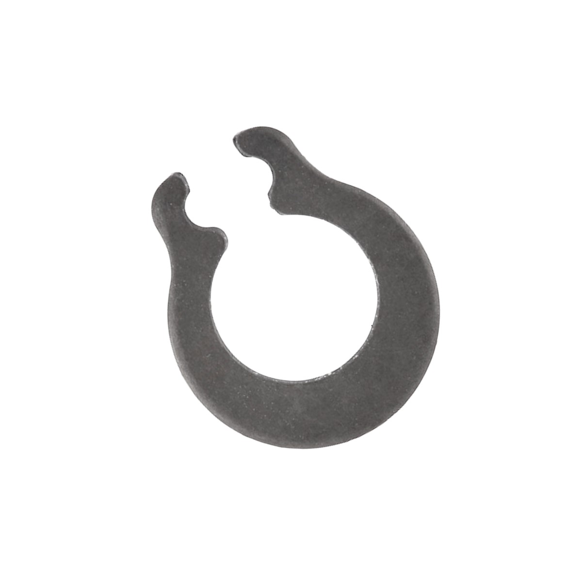
E-clips are three-pronged, stamped external retaining rings designed to lock components onto a shaft by snapping radially into a machined groove. While traditional fasteners like nuts, bolts, and cotter pins require threading or drilling, an E-clip slides on from the side without any axial movement. This simple piece of spring steel provides a tight, high-strength shoulder that prevents components from slipping or vibrating out of place. From car engines to small electronics, these tiny fasteners keep modern machinery moving smoothly.

Anatomy of an E-Clip:

An E-clip gets its name directly from its visual resemblance to the letter “E”. Unlike standard C-clips or circular snap rings, it features a unique three-pronged geometric layout:

  • The Outer Ring: Acts as the flexible backbone that springs open during installation.
  • The Central Tang: Slides directly into the deepest part of the shaft groove.
  • The Two Outer Prongs: Grip the outside walls of the groove to lock the clip securely against centrifugal or axial forces.

Because they do not have small “lug holes” at the ends like standard circlips, they do not require specialised circlip pliers to use. Instead, their open side allows for quick lateral pressure installation.

Key Benefits in Modern Manufacturing:

Engineers regularly swap out mechanical fasteners for E-clips to streamline builds and lower production costs.

Space and Weight Savings

Traditional nuts and bolts require threaded extensions, which add bulk. E-clips sit completely flush inside the machined groove, drastically shrinking the overall footprint and weight of the mechanical assembly.

Side-Mounting Capabilities

Standard retaining rings must slide all the way from the end of a shaft to its final destination. If a shaft is blocked by other tightly packed components, axial installation is impossible. E-clips solve this by snapping on radially right from the side.

No Threading Required

Machining threads onto a tiny rod is time-consuming and expensive. Creating a simple smooth radial groove for an E-clip eliminates complex tapping and machining processes entirely.


Technical Specifications and Variations

Manufacturers follow strict industrial guidelines to guarantee performance safety across different environments.

Specification TypeStandard Metric (e.g., DIN 6799)Imperial (Standard N1500)
Measurement FocusSized by the exact groove diameter.Sized by the outer shaft diameter.
Common MaterialsCarbon Spring Steel, 420 Stainless Steel, 316 Stainless Steel Carbon Steel, Beryllium Copper, Zinc-plated finishes.