Author Archives: Caleb Components

Grip Rings: The Hidden Hero of Grooveless Shafts

When building or repairing machinery, we often take the smallest fasteners for granted. Standard circlips and retaining rings usually require a pre-machined groove on a shaft to sit correctly. But what happens if you cannot machine a groove? Or what if doing so blows past your production budget?

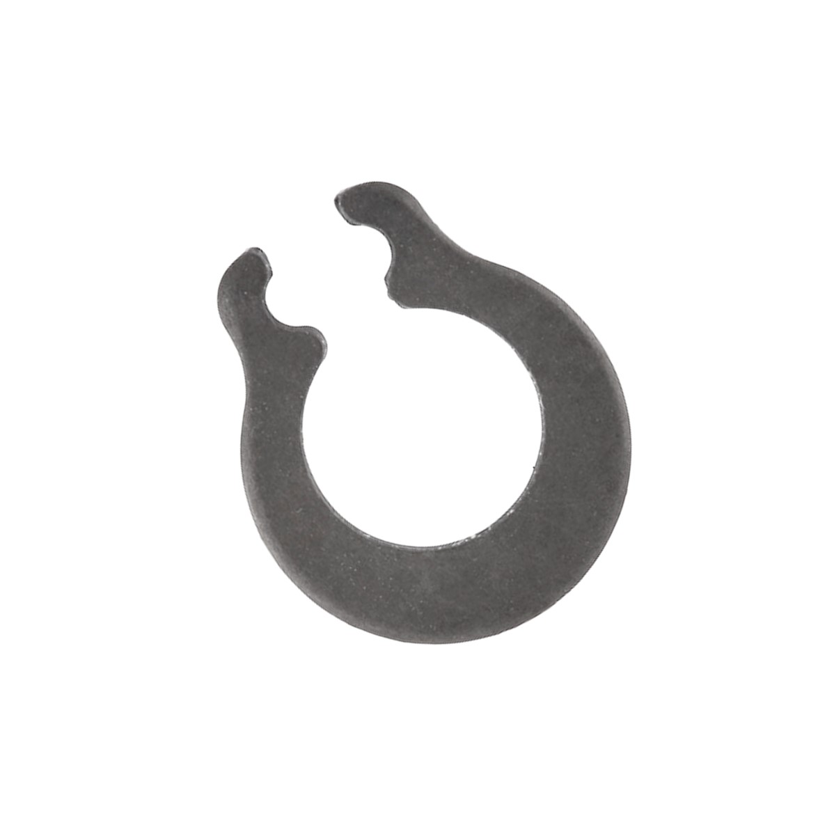
Enter the M1440 Grip Ring series, a specialized line of self-locking, axially fitted metric circlips designed specifically to provide strong retention on shafts without pre-machined grooves. By relying purely on frictional grip and high radial pressure, these unassuming components act as a powerful fastening alternative across countless industrial applications.

What Makes the M1440 Grip Ring Unique?

Unlike a standard DIN 471 external circlip that relies on a channel to hold its place, the M1440 series is engineered with a large section height. This design results in massive gripping pressure applied directly to the surface of the plain shaft.

   [ Standard Circlip ]           [ M1440 Grip Ring ]
     Requires Groove                 Grooveless Shaft
       ___       ___                    ___________

      |   |_____|   |                  |   _____   |
=====>|   |     |   | =====>      ====>|  |     |  |====>

      |___|  _  |___|                  |__|_____|__|
             |                               |
       Seated in Groove                Frictional Grip

A major engineering benefit of the M1440 design is its tapered section. When fitted, this taper ensures even contact distribution around the entire circumference of the shaft. Because the ring is not stretched beyond its elastic limit during installation or removal, it can be re-used multiple times without losing its gripping force or damaging the shaft.

You will find M1440 grip rings quietly doing heavy lifting behind the scenes across a vast range of sectors:

  • Automobile Assemblies: Securing lightweight linkages and pivot pins where structural machining is impractical.
  • Industrial & Manufacturing Machinery: Acting as quick-fix or adjustable retaining stops on automated conveyor lines and guide rods.
  • Office & Domestic Furniture: Holding rotating wheels, casters, or small internal hinges firmly in place on plain steel pins.

Installing Spring Tension Pins (Roll Pins)

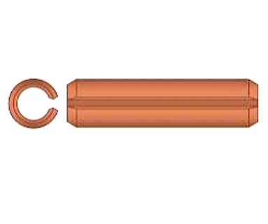
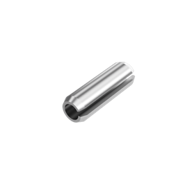
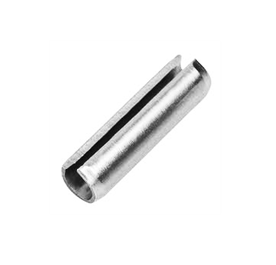
To install a spring tension pin (also known as a roll pin or coiled pin), you must align the host holes precisely and drive the oversized pin in using a dedicated roll pin punch and a hammer. Because spring pins are manufactured slightly larger than the hole, they compress upon entry to create a permanent, vibration-resistant interference fit

Essential Tools

  • Roll pin punches: Unlike standard flat punches, these feature a small center pilot ball or nub that keeps the punch centered and prevents the hollow pin from collapsing or flaring.
  • Ball-peen hammer or mallet: Used for driving the punch.
  • Vise grips or pliers: Highly useful for gripping and stabilizing small pins during the initial start.
  • Lubricant (Optional): A drop of light oil can ease insertion into tight metal holes.

Step-by-Step Installation Guide

   Roll Pin Punch (With Pilot Ball)
         [======]
           |||  <-- Pilot ball fits inside the pin
          [===]

          |   | <-- Spring Tension Pin (Oversized)
          |___|
         _______
      ===|     |=== <-- Aligned Host Components

         |_____|

1. Confirm Pin Sizing

Always select a pin matching the nominal size of your drilled hole. For instance, a 5mm spring pin is explicitly intended for a 5mm hole, though its uncompressed resting diameter will measure slightly larger.

2. Align the Components

Thoroughly align the holes of the internal shaft and external housing. If the components are misaligned, the pin will bind, bend, or score the inside of the hole. Use a regular punch or alignment tool to temporarily hold them in position if necessary.

3. Start the Pin

Place the chamfered (tapered) end of the pin into the hole.

  • Pro Tip for Small Pins: Small pins are notorious for flipping or dropping. Use a pair of vise grips or locking pliers to lightly pinch the pin near its insertion tip. This lets you hold the pin steady without risking your fingers.

4. Drive the Pin Home

Place your roll pin punch squarely over the exposed end of the pin. Deliver light, controlled, and perfectly straight hammer strikes. Keep driving the pin inward until it sits flush with—or is centered equally within—the host material

High Performance Under Pressure: Disc Springs in Aerospace Engineering

In aerospace design, every component must deliver maximum reliability with minimum weight. Space is limited, and environmental conditions are extreme. Disc springs—also known as Belleville washers—are conical-shaped metallic rings that solve these precise engineering challenges. They store and release mechanical energy along their axial axis, offering unique force-displacement characteristics that standard coil springs cannot match.

Here is an analysis of how these compact components support critical aerospace systems.

Exceptional Load-Bearing Capabilities:

Disc springs are uniquely suited for aerospace applications due to their high force-to-space ratio.

  • Space Efficiency: They generate immense force within a highly compact physical footprint.
  • Customisable Stack Dynamics: Engineers can stack discs in series to increase deflection, or in parallel to multiply the load capacity.
  • Predictable Deflection Curves: They can be engineered to exhibit linear, regressive, or progressive load characteristics based on the application’s specific mechanical requirements.

Critical Aerospace Applications

Disc springs act as vital safeguards across multiple aircraft and spacecraft subsystems.

Flight Control Systems:

In hydraulic actuators and primary flight control linkages, disc springs maintain constant tension. They take up mechanical backlash, ensuring that pilot inputs or automated flight corrections remain precise and instantaneous without slop in the system.

Landing Gear Assemblies:

Aircraft landing gear must absorb massive kinetic energy during touchdown. Disc springs are utilized within shock absorption systems and braking mechanisms. They provide heavy-duty dampening and maintain consistent pressure on brake packs as friction materials wear down over time.

Cryogenic and High-Temperature Valves:

Spacecraft and rocket propulsion systems rely on valves that operate anywhere from cryogenic liquid fuel temperatures to extreme exhaust heat. Disc springs exert continuous sealing pressure on valve seats, automatically compensating for the thermal expansion and contraction of surrounding metals to prevent catastrophic leaks.

Bolt Preloading and Structural Joints:

Aerospace structures experience severe vibration during flight and launch. Disc springs are placed under bolt heads and nuts to maintain a constant pre-load. This prevents structural fasteners from loosening under cyclical stress and vibration.

Advanced Metallurgy and Material Selection:

Standard carbon steel fails under the extreme demands of flight. Aerospace disc springs utilize advanced alloys engineered to survive corrosive environments, high radiation, and thermal spikes.

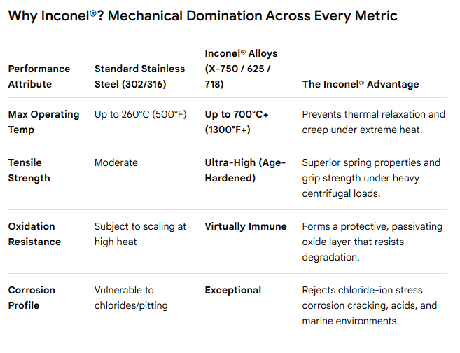
  • Inconel (X750 and 718): Chosen for its exceptional strength and resistance to relaxation at high temperatures.
  • Titanium Alloys: Utilized when weight reduction is the primary design driver, offering an excellent strength-to-weight ratio.
  • Stainless Steels (e.g., 17-7 PH): Selected for high fatigue resistance and excellent corrosion protection in atmospheric flight.

Strict Manufacturing and Quality Standards:

Failure is not an option in aerospace engineering. The production of aerospace-grade disc springs requires meticulous quality control processes.

  • Precision Machining: Involves tight tolerances on the inner diameter, outer diameter, and material thickness to ensure predictable force profiles.
  • Shot Peening: A surface treatment process that introduces compressive residual stresses, significantly increasing the fatigue life of the spring under cyclic loading.
  • Rigorous Non-Destructive Testing (NDT): Magnetic particle or liquid penetrant testing is standard practice to detect microscopic surface defects before deployment.

Contact us today for a free quotation.

A Deep Dive into E-Clips

E-clips are three-pronged, stamped external retaining rings designed to lock components onto a shaft by snapping radially into a machined groove. While traditional fasteners like nuts, bolts, and cotter pins require threading or drilling, an E-clip slides on from the side without any axial movement. This simple piece of spring steel provides a tight, high-strength shoulder that prevents components from slipping or vibrating out of place. From car engines to small electronics, these tiny fasteners keep modern machinery moving smoothly.

Anatomy of an E-Clip:

An E-clip gets its name directly from its visual resemblance to the letter “E”. Unlike standard C-clips or circular snap rings, it features a unique three-pronged geometric layout:

  • The Outer Ring: Acts as the flexible backbone that springs open during installation.
  • The Central Tang: Slides directly into the deepest part of the shaft groove.
  • The Two Outer Prongs: Grip the outside walls of the groove to lock the clip securely against centrifugal or axial forces.

Because they do not have small “lug holes” at the ends like standard circlips, they do not require specialised circlip pliers to use. Instead, their open side allows for quick lateral pressure installation.

Key Benefits in Modern Manufacturing:

Engineers regularly swap out mechanical fasteners for E-clips to streamline builds and lower production costs.

Space and Weight Savings

Traditional nuts and bolts require threaded extensions, which add bulk. E-clips sit completely flush inside the machined groove, drastically shrinking the overall footprint and weight of the mechanical assembly.

Side-Mounting Capabilities

Standard retaining rings must slide all the way from the end of a shaft to its final destination. If a shaft is blocked by other tightly packed components, axial installation is impossible. E-clips solve this by snapping on radially right from the side.

No Threading Required

Machining threads onto a tiny rod is time-consuming and expensive. Creating a simple smooth radial groove for an E-clip eliminates complex tapping and machining processes entirely.


Technical Specifications and Variations

Manufacturers follow strict industrial guidelines to guarantee performance safety across different environments.

Specification TypeStandard Metric (e.g., DIN 6799)Imperial (Standard N1500)
Measurement FocusSized by the exact groove diameter.Sized by the outer shaft diameter.
Common MaterialsCarbon Spring Steel, 420 Stainless Steel, 316 Stainless Steel Carbon Steel, Beryllium Copper, Zinc-plated finishes.

Grade 420 Stainless Steel: The Ultimate Balance of Hardness and Fresh-Water Corrosion Resistance

Grade 420 stainless steel is a high-carbon martensitic stainless steel designed to deliver exceptional hardness, high strength, and moderate corrosion resistance. Often referred to as “surgical steel,” this alloy can be heat-treated to achieve a rockwell hardness of up to 50 HRC, making it the premier choice for cutting edges, wear surfaces, and high-stress mechanical parts.

💡 Key Characteristics & Properties

  • High Wear Resistance: Thanks to its high carbon content, Grade 420 can be hardened through quenching and tempering to resist severe abrasive wear.
  • Moderate Corrosion Resistance: It offers good resistance to fresh water, mild acids, alkalis, air, and food acids, but only when it is fully hardened and polished.
  • Magnetic Nature: Unlike austenitic grades (like 304 or 316), Grade 420 is highly magnetic in all conditions.
  • Limited Weldability: Due to its hardening characteristics, welding Grade 420 is difficult and requires extensive pre-heating and post-weld annealing to prevent cracking

🛠️ Common Applications

Grade 420 is widely used in industries requiring sharp edges, high tensile strength, and hygienic properties:

  • Cutlery and Blades: Chef knives, hunting knives, and industrial shear blades that must hold a sharp edge.
  • Medical Instruments: Surgical tools, dental instruments, and forceps due to their hardness and ability to withstand repeated sterilization.
  • Mechanical Components: Valve parts, pump shafts, needle valves, pistons, and ball bearings subjected to continuous friction.
  • Plastic Moulds: Injection moulds that require high polishability and resistance to abrasive plastics.

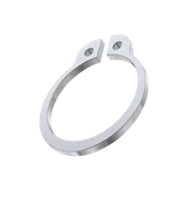
Our External and Internal Circlips are available in 420 Stainless, and available to order online.

Ultimate Guide to Preload Disc Springs: Enhancing Bearing Longevity

Preload disc springs are specialized, conically-shaped washers designed to apply a continuous axial force to bearings and mechanical assemblies. By maintaining constant tension, these components take up internal clearance, eliminate play, and significantly reduce noise and vibration.

Here is everything you need to know about how preload disc springs optimize mechanical systems.


💡 Why Bearing Preload Matters

In rotating machinery, ball bearings require a specific amount of tension to operate efficiently. Without proper preloading, ball bearings experience several mechanical issues:

  • Mismatched Rotation: Balls slide or skid instead of rolling properly, causing rapid wear.
  • Axial Play: Unwanted movement along the shaft damages precision.
  • Resonance: Excessive vibration shortens the lifespan of surrounding components.

Preload disc springs solve this by maintaining a constant, predictable load that keeps the rolling elements firmly seated in their raceways.


⚙️ Key Technical Benefits

  • Compensates for Thermal Expansion: As operating temperatures rise, shafts expand. Disc springs flex to absorb this dimensional change without overloading the bearing.
  • High Force in Compact Spaces: Unlike standard coil springs, disc springs generate massive axial force while occupying minimal linear space.
  • Configurable Performance: You can stack disc springs in different arrangements to modify performance:
    • In Series (Opposing directions): Increases total deflection (travel) while keeping the force the same as a single spring.
    • In Parallel (Same direction): Increases total force while keeping deflection the same as a single spring.

🛠️ Common Industrial Applications

Preload disc springs are essential components across high-precision and heavy-duty industries:

  • Electric Motors: Minimizes rotor shaft float and reduces operational noise.
  • Machine Tool Spindles: Ensures extreme axial rigidity for precise cutting and milling.
  • Automotive Drivetrains: Maintains clutch and transmission alignment under variable loads.
  • Pumps and Compressors: Absorbs axial thrust forces generated by high-velocity fluids.

The Simple Genius of Terry Clips: Engineering, History, and Applications

Few hardware components achieve the status of a generic trademark, but the Terry Clip (Tool Clip) stands alongside items like the Hoover or the Allen key. Celebrated for its simplicity and mechanical efficiency, this modest clip remains an essential fixture in residential garages, commercial workshops, and heavy manufacturing.

      __     __       <- Flexible Spring Arms
     /  \___/  \

    |           |     <- Grips Cylindrical Objects
    |     O     |     <- (Tool handle or pipe)
     \   ___   /

      |_|   |_|
       |  O  |        <- Mounting base with screw hole
       +-----+

The History: From Redditch to the World

The story of the Terry clip begins in Redditch, Worcestershire, England in 1855. originally manufactured wire hooks and springs, pulling from the region’s established expertise in handling steel wire for needle making.

By the early 20th century, the rise of the safety bicycle created a unique problem: cyclists needed a reliable way to carry handheld tire pumps without them rattling loose or falling into the spokes. Herbert Terry & Sons answered this by stamping high-tensile spring steel into a custom “C” or “U” shape profile. The fastener grabbed the pump tightly using raw kinetic tension, yet allowed the rider to instantly yank it free in an emergency.

As the decades progressed, the company expanded this fundamental design concept into automotive accessories, exercise gear, bicycle saddles, and the globally famous Anglepoise lamp.

Mechanical Design and Material Science

The high utility of a classic Terry clip stems directly from its engineering:

  • Spring Steel Architecture: True industrial Terry clips are manufactured using high-carbon spring steel or manganese steel. This material allows the arms of the clip to repeatedly flex wide open when an object is pushed inside and immediately snap back tightly to its resting parameter without losing its structural memory or clamping force.
  • Surface Treatments: Because carbon steel is vulnerable to oxidation, manufacturers apply protective finishes. The most common configuration is Bright Zinc Plating (BZP), which offers robust rust defense for garage environments. For premium marine or medical deployments, solid stainless steel is utilized.
  • Protective Coatings: Modern variations often feature a spring-steel core treated with an exterior skin of polyvinyl chloride (PVC), nylon, or rubberized coatings. These protective layers increase frictional grip while preventing the metal from scratching delicate surfaces, such as polished copper piping or carbon fiber shafts.

Key Variations: Open vs. Closed Type

While the mechanics are identical, Terry clips are categorized into two primary form factors:

1. Closed Type (Wide Base)

Closed-type clips feature extended metal bands at the anchor point that loop entirely around to create a completely enclosed circular boundary at the bottom. This design distributes heavy physical loads across a wider surface area. They are the default pick for mounting heavier items vertically, like industrial breaker bars or heavy sledgehammers.

2. Open Type (Narrow Base)

Open-type variants use a streamlined, narrow mounting profile where the spring arms stem directly up from a single central anchor screw. This compact footprint makes them ideal for tight spaces, small hand tools, or routing lines where horizontal real estate on the backing board is restricted.

Universal Applications

Thanks to their flexible design footprint—ranging from tiny 6mm diameters up to large 100mm variations—Terry clips are vital across multiple modern fields:

  • Workshop and Garage Organization: Keeping screwdrivers, chisels, torque wrenches, and brooms perfectly indexed on tool boards or shadow walls.
  • Plumbing and Infrastructure: Serving as durable wall hangers to secure copper or plastic conduit lines, while isolating the pipe from vibration and chafing.
  • Automotive and Transit: Holding emergency fire extinguishers, flashlights, or tools inside fleet trucks, off-road vehicles, and vintage car trunks.
  • Structural Framing: Serving as fast-assembly anchor joints for modular aluminum frames, such as temporary commercial gazebos or backyard trampoline enclosures.

Extractable Dowel Pins: The Engineer’s Guide to Reusable Alignment

Extractable dowel pins (also known as pull dowel pins) are specialized, precision-ground fasteners used to accurately align, position, and hold machine components together while allowing for easy removal from blind holes. Unlike standard dowel pins, which require an exit hole to be punched out from behind, extractable dowel pins feature an internal thread. This internal thread allows engineers to easily pull the pin out from the front using a matching screw or a specialized slide-hammer extraction tool.


How Extractable Dowel Pins Work

Standard dowel pins work beautifully in through-holes. However, when a dowel pin is pressed into a blind hole (a hole that does not go all the way through the material), removing it later becomes a destructive and frustrating nightmare.

Extractable dowel pins solve this specific issue through a simple design:

  • Internal Threading: The core of the pin is tapped with a standard metric or imperial internal thread.
  • Air Vent Flat: Most pull dowels feature a small ground flat side or an axial vent groove. This prevents air pressure from trapping the pin inside a blind hole during installation or removal.
  • Tapered Options: Some extractable dowels feature a slight taper, making them even easier to release from heavy-duty industrial machinery.

To extract the pin, a technician simply threads a bolt, threaded rod, or slide-hammer tool into the top of the pin and pulls it straight out without damaging the surrounding mating surfaces.


Key Benefits in Industrial Applications

Implementing extractable dowel pins over standard fasteners offers three primary advantages:

  • Effortless Maintenance: They completely eliminate the need for drilling out stuck pins, reducing machinery downtime from hours to seconds.
  • Component Protection: Because removal forces are applied inline via the thread, the surrounding precision-machined holes are protected from scratches, warping, or widening.
  • Infinite Reusability: Manufactured from hardened alloy steel or stainless steel, these pins can be inserted, extracted, and reused across hundreds of maintenance cycles

Technical Specifications to Consider

When sourcing extractable dowel pins for a project, pay close attention to these critical dimensions:

  • Nominal Diameter & Tolerance: Usually ground to precise tolerances (such as m6 or h6) to ensure an interference fit or tight clearance fit.
  • Thread Size: Standard sizing dictating the pull tool needed (e.g., an M6 diameter pin might feature an M3 or M4 internal thread).
  • Hardness Rating: Typically hardened to HRC 58-62 to ensure the extraction threads do not strip out under high pulling forces.

How Starlock Washers Work

Starlock Washers are a highly efficient type of push-on fastener used to permanently grip smooth, unthreaded cylindrical shafts. Unlike standard washers that sit under a nut to distribute pressure, Starlock washers function as standalone retaining clips that bite deeply into a shaft to prevent components from working loose.

Here is a comprehensive breakdown of how they work, their key variations, and where they are most commonly used.

Starlock Washers feature a unique, angled internal tooth design that points inward.

  • Zero Threading Required: You can slide the washer down a plain metal, plastic, or composite axle without cutting any threads.
  • Instant, Permanent Lock: As the washer pushes onto the shaft, the inner teeth deflect outward. The moment any back-off force is applied, those sharp teeth bite aggressively into the shaft.
  • Vibration Resistant: They exert continuous initial tension, making them highly effective at preventing parts from rattling loose on moving machinery.
  • One-Way Assembly: Once secured, they are nearly impossible to slide back off without destroying the fastener.

Common Applications

Because they eliminate the time and cost of machining snap-ring grooves or threading shafts, you will find them everywhere in consumer and industrial assemblies:

  • Wheeled Goods: Safely retaining the wheels on the smooth metal axles of prams, pushchairs, toy cars, and hand trucks.
  • Automotive & Aerospace: Securing interior panels, insulation covers, and light mechanisms.
  • Domestic Hardware: Frequently found on the standard square shafts of garage door handles.
  • Manufacturing: Pushing onto precision-machined tubes, cast parts, or plastic studs during fast-moving automated assembly lines.

Browse our full range of Starlock Washers Online:

The Unsung Hero of Machinery: A Complete Guide to Key Steel

When you look at a piece of heavy machinery, a vehicle engine, or an industrial pump, your eyes are naturally drawn to the massive components: the spinning shafts, the heavy gears, and the roaring motors.

But deep inside those connection points lies a tiny, unassuming rectangular bar that keeps the entire system from spinning out of control.

It is called key steel. Without it, modern mechanical power transmission would grind to a halt. Here is everything you need to know about this critical engineering material.


What is Key Steel?

Key steel (often referred to as key stock) is a high-quality, precision-drawn steel bar used to manufacture mechanical keys. These keys are inserted into a matching slot—known as a keyway—cut into both a rotating machine shaft and the hub of a component (like a gear, pulley, or sprocket).

The key acts as a mechanical lock. It prevents relative rotation between the two parts, ensuring that when the shaft turns, the gear turns with it. If the machine experiences an extreme overload, the key is designed to fail or shear first, protecting much more expensive components from catastrophic damage.


Why the Right Material Matters

You cannot just cut a piece of scrap metal and use it as a machine key. Key steel is specifically engineered to meet strict dimensional and physical requirements.

  • Dimensional Precision: Key steel is manufactured to incredibly tight tolerances. Because it must fit perfectly into a keyway without slipping or jamming, it is typically drawn with a minus tolerance (meaning it is exactly the nominal size or a fraction of a millimetre smaller).
  • High Tensile Strength: It must withstand immense torsional (twisting) forces. Standard mild steel would twist or deform under heavy industrial loads, leading to loose components and machine failure.
  • Machinability: While tough, key steel must still be easy enough to cut, file, and fit by maintenance engineers working in the field or in a machine shop.